Custom Cold Air Intake – What Are The Benefits?
October 14, 2024Is it worth making a custom cold air intake? And if so, what are the main design goals and what changes need to be made?
Worth It? – Cold Air Intake
There is an article dedicated to answering this question which you can see here. It details what needs to be measured and how.
There is another reason for fitting a cold air intake which that article does not cover and that is changed intake manifold, changed air filter location, different turbo, basically if the mechanical parts of the intake have been changed which makes it impossible to use the factory pipework.
Assuming a cold air intake is needed
What benefits/improvements/targets should be aimed for?
The article linked to above explains this. To repeat here, the best cold air intake will have zero vacuum at the throttle body (NA engines) or zero vacuum at the turbo inlet on turbo motors.
Intake temps should be within 10 degrees C of ambient normally and preferable within 20 degrees C of ambient under hard use.
In both cases, it is impossible to be too good. If we can get a bit of positive pressure into the intake that is amazing and the more the better. And if we can get temps the same as ambient, again, amazing.
Those are the attributes of the perfect custom cold air intake, no vacuum and low temps, but what changes do we need to make except the piping/bands/filter/filter location, in other words, what electronic changes do we need to make?
More specifically, is sensor placement important?
There is an article here which goes over the importance of MAF sensor placement. In short, good Mass Air Flow sensor placement is key for a properly running engine.
I believe there is probably consensus that MAF sensor placement is important. On the subject of IAT and MAP sensor placement I’m not so sure. Perhaps it’s not something people have considered as being a possible issue.
I argue that the position of the IAT and of the MAP sensor is equally important to that of the MAF.
MAP sensor placement on the subject of CAIs is a mute point but the relevance of IAT sensor placement may not be (depending on the vehicle/engine ECU).
An IAT sensor is measuring the air, just like a MAF (its not measuring the same aspect of the air but it is measuring the air all the same) and for that reason the positioning should be considered just as much as MAF placement. At the end of the day, I don’t think we can reach a point where the IAT sensor placement is too good, but I think it’s possible to have the IAT sensor mounted in a place that is bad.
Sensor Calibration – Custom Cold Air Intake
We’ve made our (hypothetical) custom intake and we have made some big changes. We have big bore pipework all the way up to the turbo. Before it was 60mm pipework feeding our 50mm turbo inlet, with an 80mm MAF. Now we are using a 90mm MAF, 80mm pipework, reducing to 76mm pipework, going down to our turbo inlet. With the new setup intake temps are down and we have zero pressure drop at the turbo inlet. Both improvements over the factory setup.
Two Questions
The easy one first, how can we make our bigger MAF housing work without remapping the engine ECU? We can rescale the MAF sensor signal using something like the MoviChip MAF CAL.
Second question, if we are rescaling the MAF, have we actually improved anything? If the new MAF is reading 2 volts but we need to change this voltage to what the old MAF was giving under the same circumstances, are we back to square one?
In a word no.
When we rescale the MAF we are simply giving the engine ECU a correct picture of the air entering the engine. Yes we are matching the new MAF signal to the old MAF signal but the conditions are not actually the same.
With the new custom intake we are seeing more flow (because of less restriction and lower temps) at the same RPM and engine load. The intake has made the engine more efficient. It can flow more air at lower loads and lower RPMs.
When we are matching the old MAF signal to the new, yes the engine is flowing the same amount of air, but with the more efficient setup, this is happening with less load on the engine.
Okay, but why did we change the MAF housing?
There are two reasons for upgrading a MAF sensor housing.
The first is that the smaller housing was a restriction (unlikely for modest power upgrades on modern cars). The second reason is that the MAF sensor in the housing was maxxing out. At peak airflow through the engine, the MAF sensor was hitting it’s maximum limit. Perhaps it was only able to read 95% of the true airflow, fitting a bigger housing using the same sensor allows us to lift the amount of airflow the sensor can measure.
What else do we gain from a bigger MAF housing?
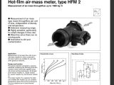
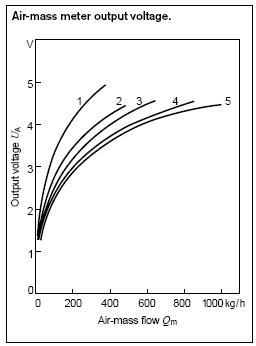
Higher resolution of air measurement at higher RPMs and loads. The HFM5 mass air flow sensor from Bosch. As airflow increases the change in sensor voltage decreases. Looking at the graph below, we can see we get massive increases in airflow for a small increase in output voltage about around 4.4 volts.
By using a larger MAF housing with MAF scaling, we can eliminate/massively reduce the chance of restriction and we can gain better sensor accuracy at higher flow rates.
Wrapping Up – Custom Intakes
Yes, a custom cold air intake can be worth making, it might even be essential if things in the engine bay have been relocated.
The goal of a custom intake is to eliminate restriction and minimise temperatures. To do this we may have to relocate air sensors and their new placement needs to be thought through thoroughly.
And to get to our ideal intake, we may need to rescale the MAF sensor to account for a larger MAF housing and/or account for a new sensor location which is better/worse than the previous location.