


This RPM Activated Switch can trigger up to two 12 volt circuits independently.
Each circuit can also use up to two 0-5 volt analog inputs as well as RPM, if need to control the circuits with more precision.
How Is it Programmed?
The CamSwitch3 RPM window switch is mounted in the engine bay and is programmed via Bluetooth using the CamSwitch3 Android App
General Usage Examples
- Camshaft activation eg VVL/VTEC
- Fan activation
- LED activation
- Additional fuel pump activation (with external relay, not included)
- Active aero parts eg diffusers, spoliers
NOTE: The CamSwitch 3 rpm activated switch can trigger circuits with current requirements less than 3 amps directly.
For circuits requiring more current, external relays must be used. These relays are not included.
**Not suitable for use with Nitrous**
Features
Trigger up to two 12 volt circuits independently using up to two sensors and/or RPM
Customise the activation of 12 volt circuits according any 0-5 volt sensor input. For example:
- Circuit activation according to engine load, steering angle and RPM.
- Switch a 12 volt circuit based on engine load, RPM and coolant temperature
- Switch a 12 volt circuit according to engine load, RPM and intake air temperature
Benefits
- Optimise performance of 12 volt circuits by activating the circuit only when it is required
- Optimise engine performance by only activating 12 volt circuits based on user specified engine operating conditions eg activating CO2 spray on an intercooler when intake temps and engine load above user programmed thresholds.
What’s Included?
CamSwitch3 RPM Activated Switch
CamSwitch3 Android App (Download)
Connector with crimps (user must build their own loom)
Manual & App
Click the tabs above to download the manual and app.
Note: the app will only work when connected to the unit. Check the video below to see how the app works.
Specific Example Usage
Camshaft Activation Conditions
-Camshaft 1 activation at 30% MAP sensor signal & over 5000 rpm & coolant temp sensor over 70% signal
-Camshaft 2 activation at 30% MAP sensor signal & over 5500 rpm & coolant temp sensor over 70% signal
Camshaft Deactivation
Deactivation for both camshafts will happen at the same time one second after MAP sensor signal drops below 30% MAP or RPM drops below 5000rpm.
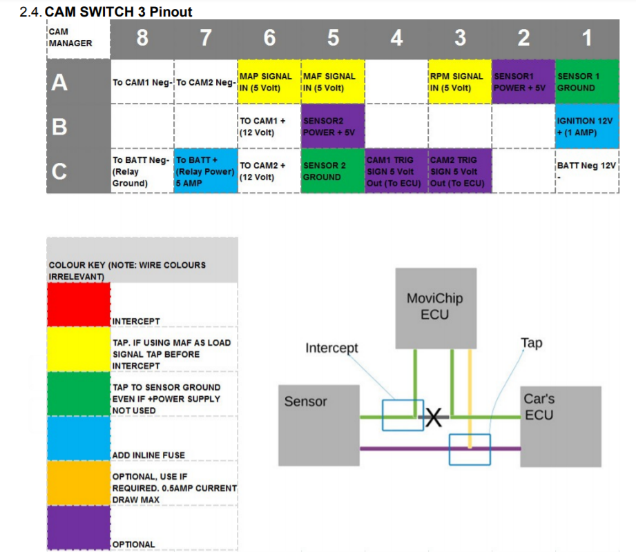
Wiring
Inputs
1 x power 12-24 volts with 1 amp inline fuse (fuse not included) to battery positive
2 x 5 volt sensor inputs
1 x 5-30 volt switched timing signal (eg coil on plug activation signal). 0.5 or 1 spark signals per engine revolution
Output
2 x 12 volt switched ground signal output. (3 amp per circuit max)
2 x 5 volt output (0.5 amp max). For external sensor power eg you want to use a MAP sensor but engine does not have one.
Wiring Diagram
The wiring diagram and instructions can be found in the user manual which can be downloaded in PDF
Video
This video shows the process of setting up your cam switch points.

